Part design recommendations for plastic injection moulding processes
Injection moulding of plastic parts, tips for optimising the plastic injection moulding process through design.
LOCATION OF EXTRACTORS AND INJECTION POINTS
If possible, the extractors and injection points should be located in non-visible areas of the part, as they influence the final aesthetics of the product.
CONTRACTIONS
It is important to allow allowances for material shrinkage and shrinkage in part design, given the solidification process the material undergoes. Shrinkage affects the dimensional accuracy of the part, but not only that, it also introduces internal stresses that can render the part invalid. The shrinkage rate of the part is given by the material manufacturer and has to be used in the design of the part. The following table shows some guideline values of shrinkage percentages experienced by different thermoplastic plastics.
| THERMOPLASTICS | |
| Material | % shrinkage during solidification |
| POM Acetal | 2,0 – 2,5 |
| Acrylic PMMA | 0,3 – 0,8 |
| ABS | 0,3 – 0,8 |
| Polyamide PA | 0,3 – 1,5 |
| Polycarbonate PC | 0,5 – 0,7 |
| Polyethylene PE | 1,5 – 5,0 |
| PP Polypropylene | 1,0 – 2,5 |
| Polystyrene PS | 0,2 – 0,6 |
| Rigid PVC | 0,1 – 0,5 |
| PVC flexible | 1,0 – 5,0 |
WALL THICKNESS
The wall thickness depends on the material to be injected. The minimum thickness is limited by the fact that thin-walled material has flow problems, solidifies (or cures) before completely filling the mould, and in turn increases the likelihood of air entrapment. In smaller parts, the thickness may be smaller because the flow path is also smaller. On the other hand, thicker thicknesses lead to longer solidification times, increased shrinkage and thus higher internal stresses. The following table shows the recommended maximum and minimum thicknesses for different plastics and depending on the size of the part.
| Small parts | Small parts | Large parts | Large parts | |
| MATERIALS | Average thickness | Minimum thickness | Thickness range | Average thickness |
| Thermoplastics | m | |||
| Acrylics (PMMA,PAN,ABS,SAN) | 0,99 | 0,65 | 3,25 – 6,50 | 2,5 |
| Cellulose acetates | 1,25 | 0,65 | 3,25 – 4,75 | 1,9 |
| Cellulose acetate butyrate | 1,25 | 0,65 | 3,25 – 4,75 | 1,9 |
| Ethyl cellulose | 1,25 | 0,9 | 2,50 – 3,25 | 1,6 |
| Polyamide PA | 0,65 | 0,35 | 2,50 – 3,25 | 1,6 |
| Polyethylene PE | 1,25 | 0,9 | 2,50 – 3,25 | 1,6 |
| Polystyrene PS | 1,25 | 0,75 | 3,25 – 6,50 | 1,6 |
| Polyvinyl chloride PVC | 2,5 | 1,6 | 3,25 – 6,50 | 2,5 |
It is always recommended that thicknesses should be uniform, and if a change in thickness is unavoidable, the transition should be smooth and not abrupt.


threads
The moulded threads must be dough. For a gooddesign of the injection mould, both crests and valleys must be rounded to avoid sharp edges and the non-existence of radii of agreement.

Minimum sizes should be 32 threads per inch (thread pitch greater than 0.75mm).
Threaded sockets are preferable when the pitch is fine, the diameter small and when close tolerances are required, as well as when frequent threading-unscrewing is necessary.
Thread exits must be left, and to make small female threads, it is better to leave a hole and tap afterwards.
HOLES
They can complicate (and therefore make the mould more expensive), and tend to form burrs and weld lines. The minimum spacing between holes, and between holes and the wall is 1 diameter, and conveniently at a distance of 3 diameters from the end of the part to avoid stresses, although in the case of thermosets the increase in diameter allows the minimum distances to be reduced.
Through holes are preferable to blind holes, as fixing the tap at two points improves the positioning and resistance to breakage. In addition, it is advisable to give a small taper at the base of the plug to give greater strength to the plug, at the same time as it forms a small arrangement at the entrance of the hole.
It is recommended that the holes be perpendicular to the parting line, as parallel holes require retractable cores.
In blind holes it is recommended that for thermoplastics L≤2D or L=D mm if D≤1.5 mm, and that L≤2.5D or L≤1D if D≤1.5 mm be placed in a table or other more graphic form for thermosets. To increase the depth, usestepped holes.


NERVES
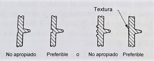
They must be used to reduce the thickness of the wall they reinforce, however, there are a number of aspects that must be taken into account. They must be thinner than the wall they reinforce to avoid marks. It is recommended that tnerves≤ 0.5-twall. Nerves should have a height of less than 1.5-twall to avoid marks. To achieve the necessary reinforcing effect with this height, the rib can be split into two smaller ones separated by a distance of twice the wall thickness. The separation from the ribs to the wall must be greater than 2-twall. The exits of the ribs should be generous (5°).
The ribs should be perpendicular to the parting line. Rib marks can be disguised by using textures.

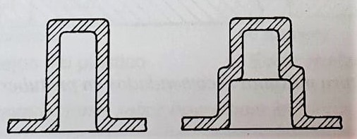
BUMPS
For protrusions the same rules apply as for ribs, but in this case the maximum recommended height is 1.5-twall and the width should be less than 0.5-twall..
If possible, the protrusions should be placed in the corners to facilitate filling. If it is insulated, a rib is placed to facilitate filling.
Try to avoid placing protrusions at the top of the mould to avoid air entrapment. If the protrusions are large, they should be hollow to maintain the uniformity of the walls.
An angle of 5° should be used, as for the nerves.

OUTGOING
Overhangs that are not perpendicular to the parting line require the use of injection moulds with sliding centre parts, with a consequent increase in costs. The external bosses can be placed on the parting line to simplify the mould.
INSERTS
Inserts are useful for providing localised reinforcement. They are generally inexpensive, but they make the process more expensive and should be avoided.
Avoid sharp edges of the insert in the part embedded in the plastic. The slits in the insert must be large enough to allow the plastic to reach all parts.
Threaded inserts should be positioned perpendicular to the parting line to simplify the mould. Irregular inserts should be positioned with their axis in the parting line of the plastic injection mould.
The embedded length of the insert must be 2-D or greater.
Inserts are often placed embedded in a protuberance. If the outer diameter of the insert is less than 6 mm, then Dprotub. ≥2-D; if the outer diameter of the protrusion is greater than 6 mm, then the wall thickness of the protrusion should be between 50 and 100% of the insert diameter.
It is sometimes convenient to make the insert after moulding, which avoids problems of contamination of the surface of the insert in contact with the plastic during the moulding process, simplifies the mould and eliminates the possibility of the mould being damaged by the insert. Inserts can be made while the material is still hot, or with ultrasonic techniques.
In the case of threaded inserts, the threaded part must be moved away from the surface to prevent the plastic flow from reaching it. Chamfers in the plastic material around the inserts should also be avoided.
13 April, 2021
Siguiente artículo:
Avances en la Selección de Aditivos para la Inyección de Plásticos: Mejorando el Rendimiento y la Sostenibilidad